Begin With Ground, Use, and Local Review
A modular cabin may arrive largely assembled, yet its support system is a site-specific construction decision. Before choosing piers, a slab, or skids, document the ground, building use, location, expected occupancy, drainage, wind exposure, installation access, and whether the unit is intended to move again. A foundation is not merely a place to put a cabin. It must transfer loads, resist relevant movement, support connections, and remain usable through expected site conditions.
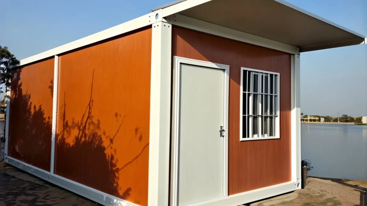
Ask the destination project team to prepare a plot plan and identify the engineer, surveyor, installer, utility providers, and local reviewing authorities. Record what is known, what is assumed, and what still needs investigation. Treat a marketing photograph or a previous project in another country as background only, not a design precedent. The unit's actual frame and intended support points matter more than a general product label.
Foundations, anchoring design, local installation, utility connections, permits, inspections, and final approval are destination-side responsibilities. The factory can supply product-side drawings and handling information for review, but it cannot determine a site-specific legal or engineering outcome remotely. Use this comparison to build a proper question list, not to select a foundation without local professional review.
Investigate Bearing, Settlement, and Slope
Ground that looks firm at the surface may contain fill, soft layers, expansive clay, buried services, rock, or seasonal groundwater. A qualified local professional should decide whether a ground investigation is needed and what design parameters it must establish. A walkover is useful for locating drainage paths and access constraints, but it does not establish allowable bearing or settlement behavior. Soil conditions may change over short distances.
Ask for a survey showing levels, slopes, boundaries, drainage features, service corridors, and the proposed cabin positions. The structural designer should coordinate that information with actual unit reactions, support geometry, occupancy and environmental actions. Concentrated frame reactions differ from an evenly distributed floor load. Differential settlement can affect door operation, cladding joints, floor level, and utility connections even without obvious overall movement.
On sloping land, consider cut-and-fill stability, erosion, safe access beneath a raised cabin, and drainage from the uphill side. A shallow leveling pad does not automatically solve slope or unstable-fill problems. The local engineer must select a support system suited to the investigated ground and the applicable jurisdiction. Request the factory's specified bearing and support locations before drawings are finalized; never infer them from container corner geometry alone.
Piers and Individual Pads
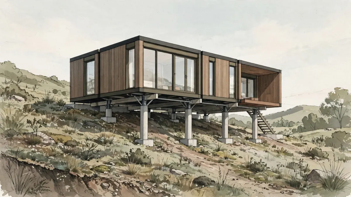
Piers or separate pads carry loads at designed locations while leaving ground between supports relatively open. This can allow underfloor inspection, routing of some services, and a raised floor where that arrangement is appropriate. It also places particular importance on support alignment, connection details, and the stability of each bearing point. A cluster of informal blocks is not the same as an engineered pier foundation.
The destination designer must determine pad dimensions, depth, reinforcement where required, erosion protection, frost response, and lateral and uplift restraint. In a sloping or exposed site, the pier-to-frame connection and ground-to-pier connection both matter. Ask how each pier will be surveyed, built, inspected, and adjusted before the module is lifted into place. A mismatch among supports can twist the frame or leave unintended gaps.
A raised cabin can require separate planning for steps, ramps, landings, guarding, accessibility, pest exclusion, fire considerations, and the protection of exposed plumbing. The accessible underside may be an advantage for maintenance, but it can expose pipes and components to weather or impact. Check whether the factory requires continuous supports, specified positions, or restrictions on span. Only the approved unit information and a local design can establish whether point support is suitable.
Slabs and Continuous Support
A slab provides a continuous working surface and may simplify certain access or housekeeping arrangements. It is not automatically appropriate for every cabin: the structural frame may still transmit load at selected rails or positions, and the site may require measures against moisture or ground movement. The local engineer should consider subgrade preparation, compaction, drainage, reinforcement, edges, joints, moisture barriers, and any relevant insulation.
A continuous base needs coordination with service penetrations and anchor locations before concrete work starts. Conduits and wastewater lines should not collide with anchors or become inaccessible beneath the module. Ask for a dimensioned drawing that shows structural supports, doors, utility connections, drainage outlets, and the intended finished floor level. Confirm how rainwater will run away from thresholds and how the surrounding ground will meet paths and ramps.
A slab may suit a planned long-term location, but its implications for a later move should be documented. Removing a unit does not remove the slab, buried services, or responsibility for restoration. In some cases a local team may prefer a different engineered continuous footing or base rather than a full slab. The comparison should be based on loads, ground, local rules, operations, and relocation intentions, not a blanket claim that concrete is always more permanent or more secure.
Skids and Designed Relocatable Bases
Skids and runners support loads along defined lines and may facilitate a particular handling or relocation plan. They still require a suitable ground bearing surface and, where necessary, a designed restraint system. A skid is not evidence that a cabin may be left unanchored, moved repeatedly, or towed legally on a road. Those are separate technical and regulatory questions.
Clarify whether relocation means lifting once onto a new base, moving within an operating site, or repeated transport between destinations. The answer affects frame details, lifting positions, service disconnections, maintenance and route planning. Ask the factory to identify where skids contact the ground, which points are structural, and what handling arrangements apply to the selected configuration. The local team must confirm base preparation, leveling, drainage, sliding resistance, overturning resistance, and connections to anchors if required.
If a gravel or compacted platform is proposed, define its composition, preparation, inspection, and maintenance instead of calling it simply a flat surface. Record what must happen when the unit is removed: anchor release, lifting access, protection of utilities, re-use or disposal of supports, and restoration of the former site. A removable support system may help the relocation strategy, but does not eliminate planning, local permissions, transport requirements, or a new destination-side foundation review.
Wind, Sliding, Uplift, and Anchoring
Wind can apply uplift, sliding, overturning, and other actions to a modular cabin. Actual exposure depends on local conditions, topography, nearby structures, module geometry, and attachments. A cabin on open land may face different demands from one sheltered by adjacent development. There is no universal anchor count or bolt detail that can be responsibly prescribed from the product name alone.
A complete load path carries forces from the cabin frame through its connections, anchoring hardware, foundation, and underlying ground. The local structural designer should determine applicable actions and verify each part of that path. Anchor capacity cannot be considered separately from frame connections, concrete edges, support geometry, or soil. Similarly, lifting holes or shipping restraints should not be treated as permanent anchors unless specified for that purpose.
Request frame drawings and marked anchor locations, together with limitations on drilling, welding, or adding brackets. The local installer needs a written method for setting, tightening, inspecting, and recording the installed hardware. Canopies, decks, stairs, roof equipment and other site additions can introduce further loads and require their own review. Do not infer storm resistance from generic photographs, informal statements, or another region's installation; use destination-specific design and inspection.
Drainage, Water, Frost, and Corrosion
Drainage should be designed alongside the foundation rather than left for landscaping at the end. Draw the route of roof runoff, uphill surface water, overflow, and discharge beyond the cabin. Standing water may soften bearing ground or reduce access for inspection. Concentrated runoff may erode around pads and create a maintenance problem even where the original support was correctly placed.
The destination team should determine finished grades, downpipe discharge, drains, swales, and maintenance access. In frost-prone locations, locally applicable foundation depth and movement requirements need assessment. In areas with intense rainfall or high groundwater, consider saturation, overflow, and the ability to inspect support points after weather events. Coastal or industrial exposure can also call for material and connection review; neither a painted frame nor a concrete base is a substitute for exposure assessment.
Coordinate drainage with steps, accessible routes, service trenches, vehicle paths, and landscaping. Do not grade the ground so that water collects at a threshold or against a support. Identify who will install each drain, maintain it, clear debris, and inspect after major weather. These are ongoing destination-side responsibilities. The choice between piers, slabs, and skids should reflect the full surface-water plan and the maintenance capability, not only the initial site photograph.
Leveling and Structural Interfaces
The foundation must meet the actual module where its frame is intended to bear. Obtain dimensioned support geometry, reference lines, permissible construction tolerances if documented, and approved connection details. The local team should survey the prepared supports before delivery and confirm whether shims, grout, plates, or other adjustments are permitted. Unsupported improvisation can transfer forces into parts of the frame not designed to take them.
An uneven base may affect openings, joints, roof drainage, service connections, and the usability of doors. Small differences can matter at connections even when they are not visually striking. Establish hold points for checking levels, dimensions, anchor positions, and the completed installation. Record who has authority to accept or reject a deviation and who obtains revised technical instructions if the built foundation does not match the unit.
Do not drill, cut, or weld the module merely to make a poorly located anchor fit. Likewise, never assume that transport lifting points are suitable as permanent bearing points. Ask the factory to distinguish handling features from service-condition supports. The structural engineer and local installer must coordinate the final setting method with the selected foundation. Clear tolerances and sign-off procedures prevent last-minute decisions from becoming hidden design changes.
Utilities, Site Access, and Setting Sequence
Site logistics can overturn an otherwise sensible foundation choice. Identify vehicle access, turning space, overhead restrictions, unloading and lifting positions, temporary storage, and the ground support needed under lifting equipment. A local specialist should prepare any required lifting or traffic plan for the actual route, equipment, and site. The unit's transport size is not always identical to its installed size.
Map electrical supply, water, wastewater, communications, condensate, and any other intended connections before foundations are built. Identify penetration positions, isolation points, clearances, drainage falls, and access for maintenance. Check whether a proposed slab would conceal repairable services or whether raised piers would expose pipes to damage or temperature extremes. Utilities should be designed and connected by the appropriate destination-side providers and trades.
A practical sequence links site investigation, supplier drawings, local design, local review, ground preparation, foundation inspection, utility rough-ins, access checks, placement, anchoring, connections, and handover. The sequence should be adapted to actual local requirements; it is not a promise of completion time or approval. Write down which party coordinates each handoff and what evidence is required before the next activity. Delivery of a cabin is one milestone, not the same as an occupiable building.
Relocation and End-of-Use Requirements
If a future move is realistic, write it into the original project brief rather than mentioning it only during purchase negotiations. Specify whether the unit might move within the plot, travel to another prepared project, or be transported repeatedly. Different scenarios affect lifting arrangements, connection design, logistics, and the meaning of a removable foundation. A building described as mobile still requires local review whenever it is placed for use.
For each support option, record how anchors can be released, whether supports can be reused, how the unit will be inspected before moving, and how utilities can be disconnected safely. The old location may still contain concrete, trenches, drainage features, or other works requiring restoration. The new location needs its own examination of bearing ground, wind, drainage, access, and applicable rules.
Relocation should not be sold as a shortcut around site obligations. At every destination, foundations, anchoring, local installation, utilities, permits, inspections, and final approval remain with destination-side professionals and authorities. Compare support systems over the expected use and removal cycle. A slab may align with long-term occupation; removable engineered supports may align with certain moves. Neither option is automatically better without a defined use, site, and engineering basis.
Factory Information and Destination Scope
Before placing an order, ask the supplier for general arrangement drawings, actual configuration dimensions, relevant unit mass information, support and anchoring locations, lifting details, service interfaces, and restrictions on modification. Distinguish preliminary drawings from confirmed documents and ask who signs off changes. Also record what ships fitted, what ships loose, and what the destination installer must assemble. If information is unavailable, mark it pending rather than treating an assumption as a design input.
Prepare a responsibility matrix separating factory-built components and export handover from site survey, geotechnical review, structural design, foundations, anchors, road and crane access, local installation, utilities, inspection, and approval. Ask the buyer's technical lead to confirm that all destination tasks have named owners. The factory's guidance may inform those people, but it does not replace their professional duties or jurisdiction-specific requirements.
MK Mobile House's website describes the company as based in Foshan, Guangdong, China; that is a company website statement, not independently verified in this article. No inference about particular foundation approvals, service capacities, or project outcomes follows from the company's location. The actionable handoff is the agreed product information plus a documented list of unresolved site matters.
Comparison Checklist Before Release
Use a short comparative record rather than choosing by habit. For each option, ask: Does the site investigation support the concept? Are actual unit reactions and support points available? How will uplift and lateral loads reach the ground? Where will water drain? Can utilities and maintenance crews reach their connections? Can delivery and lifting equipment approach safely? What remains after removal? Who checks and accepts the completed work?
List unknowns separately from confirmed answers. A pier scheme may raise the cabin and permit service access, while requiring careful point alignment and exposed-service protection. A slab may provide a continuous surface while committing the site to additional permanent work. Skids may support a relocation strategy while still needing designed bearing and restraints. These are questions to be investigated, not measured rankings or universal recommendations.
Before shipment, obtain the final product drawings, local foundation and anchor design, documented inspection points, installation responsibilities, utility layout, and a clear handover procedure. If any critical document is missing, keep the decision open for qualified review. The defensible choice is the foundation whose load path, ground treatment, drainage, access, ongoing use, and removal plan have been reconciled for the actual destination.
Sources
- MK Mobile House — Prefab Modular Cabins for Raw Land: https://mkmobilehouse.com/blog/prefab-modular-cabins-for-raw-land/
- MK Mobile House — Coordinating Local Installers and Utility Partners: https://mkmobilehouse.com/blog/coordinating-local-installers-and-utility-partners-for-modular-cabin-projects-in-north-america/
- MK Mobile House — Shipping Container or Purpose-Built Module?: https://mkmobilehouse.com/blog/shipping-container-vs-purpose-built-module-building-logic/
- MK Mobile House — About (factory/destination responsibility descriptions, company statements): https://mkmobilehouse.com/about/
- Project-specific soil, foundation, wind, building and installation requirements: consult qualified professionals and authorities in the destination jurisdiction (no universal site rule is asserted).